Filter Media Treatment – Fall 2011

Po-Hsun Lin

Abstract:

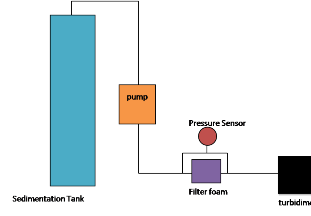
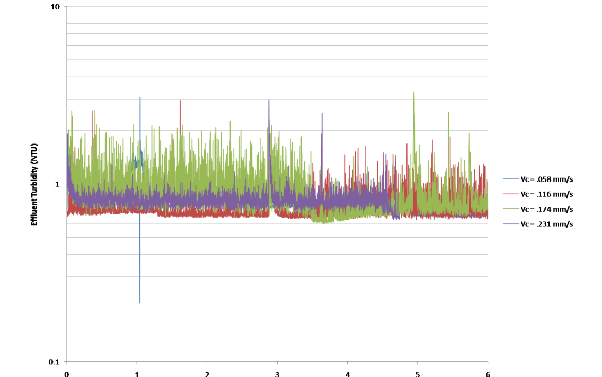
The post sedimentation addition of polyaluminum chloride (PACl) was investigated as a means to enhance particle removal efficiency in rapid sand filtration. The process modification was evaluated in laboratory studies and at the Cornell Water Filtration Plant (CWFP). PACl was continuously metered into CWFP filter influent to increase concentrations by 0.06 to 4.2 mg/L (as aluminum) during the filter-to-waste stage of the filter operation cycle to accelerate filter ripening. Lower influent PACl concentrations ranging from 0.056 to 0.43 mg Al/L were also continuously applied during filtration. In comparison to a control filter that received no PACl addition, the ripening time required decreased with PACl dose, and the incremental improvement in particle removal during filtration increased with PACl dose. The addition of 0.056 mg Al/L of PACl (the lowest concentration tested) significantly reduced initial filter ripening time at the CWFP from 10 hours to 2.5 hours, and effluent turbidity in the test filter over the 77 hour filter run was lower than the control filter by an average of 17%. Incremental head loss increase caused by the PACl feed was dose dependent and was negligible for the lowest dosage tested.

Flow Controller Linearization and Calibration, Fall 2007

Abstract:

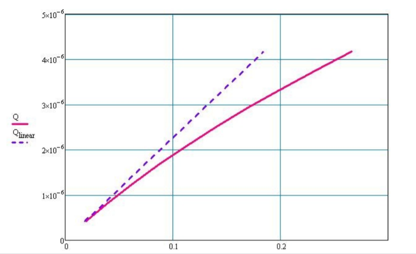
Experiments run in fall 2007 indicated that the float valve can hold back head of at least 8m with less than 0.5 cm of change occurring in the flow controller water level in the first 2 m of pressure. Data gathered in the laboratory on outflow rate has followed a linear model in the laminar flow range, but attempts to model the turbulent transition range have produced varying results. It is considered a high priority to develop a reliable model for dosing at higher flow rates, which will be used in the near future at the larger plants.

Float Valve Attenuation Factor, Summer 2008

Introduction:

Until recently, the float valves used in the AguaClara's flow controllers were slightly flawed. The float valve connector included a compression nut, which was easily misplaced or misused, leading to leaks. A new float valve would preferably have pipe threads and be able to connect to a quick connect tube fitting. Furthermore, the float on the float valve was replaced in favor of another float, complicating post manufacturing assembly. A new float valve was found with pipe threads, quick connect tube fitting and had a more appropriate valve attached. However, before the new float valve was to be implemented, a study on the attenuation factor (change in pressure from stock tank over the change in pressure in the constant head tank) was to be conducted.

Calcium Hypochlorite Dose Controller, Summer 2008

Introduction:

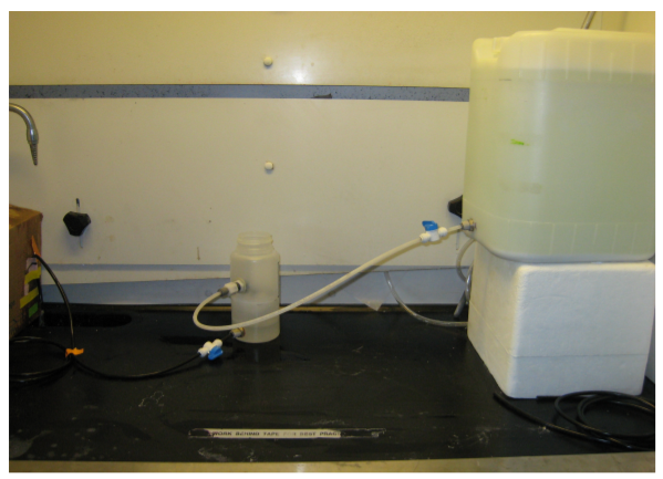
In Honduras, a Calcium Hypochlorite solution is used in the Agua Clara flow controllers to chlorinate the drinking water. Unfortunately, due to the precipitation of calcium carbonate, the system clogs, which leads to large decrease in the flow rate (and thus dosing) of the chlorinating solution. The goal of these experiments were to find the contributing factors to failure (significantly decreased flow rate) by modeling a hypochlorinator in use in Honduras.

Alum Aging Effects, Summer 2008

Introduction:

To ease plant preparation for use, it may be beneficial to create stock solutions of required chemicals days in advance of actual operation. Because certain chemical solutions equilibrate with air, they may perform better or worse with age. Using this set of experiments, it was to be determined whether an aluminum sulfate solution produces lower levels of effluent turbidity due to its age.

Demo Plant, Summer 2008

Introduction:

There are three variations of sedimentation tanks that the demo plant team can use. The purpose of these experiments were to find which sedimentation tank produced the lowest effluent turbidity when run at a number of flow rates. The preferre d tank will be used in the production of additional demo plants. The tanks are displayed below.

Flow Controller Calibration, Summer 2008

Introduction:

The flow controller design tool on the Flow Controller page is used to calculate the tube length necessary to achieve a desired flow rate with a certain head loss. It has been observed that the actual flow rates that occur when using the lengths of tube provided by the design tool were consistently much slower than they theoretically should have been. This indicated that there was some problem with the assumptions made by the design tool. The error was most likely due to one of two things. It was possible that the actual diameter of the tubing being used was slightly smaller than the diameter published by the manufacturer, or that there were significant minor losses in the flow controller not being taken into account by the assumption of a linear relationship between flow rate and head loss/tube length. It was decided that rather than having to manually calibrate every new flow controller, it would be better to come up with a new method for finding the tube length needed. The new method would need to take into account the smaller diameter of the tubing and/or the minor losses, and would predict a more accurate flow rate without having to do further manual calculations or having to cut the tube after construction of the flow controller

Rapid Mix Tube, Fall 2009

Karen Alison Swetland, Patience Ruijia Li

Abstract

During the fall 2009 semester, the main focus of the Rapid Mix Tube subteam was the development and design of a rapid mix tube system to provide adequate large and small-scale mixing of alum with the raw water source entering the plant. The system developed in the fall 2009 semester is designed for the Agalteca plant, but the ultimate design can be modified to fit into future AguaClara plants and even fit into existing plants to improve rapid mix . The design of the system evolved multiple times throughout the semester, and the current system was developed to improve upon the main problem of those initial designs: access to the small scale rapid mix orifice to clean it in case of clogging. The design of the tube was thus tailored to fix this problem, and a MathCAD file calculating orifice sizes and head loss through the system was developed. A built prototype model of the rapid mix tube was also constructed to provide a model for the construction of the rapid mix tube system, and a series of experiments (to be run using FReTA) was also designed to test the effect of the rapid mix tube system on the effluent water turbidity and to determine the need for the rapid mix tube system.

Plate Settler Spacing - Filter Foam, Summer 2009

Rachel Beth Phillipson

Abstract:

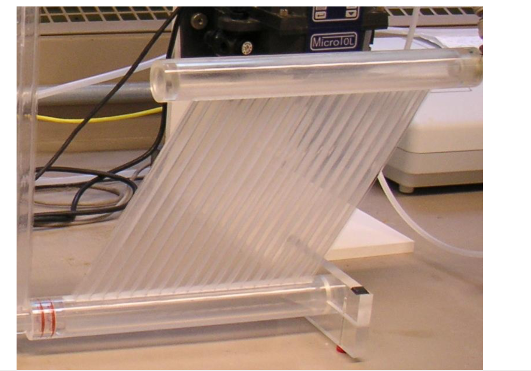
At the plants in Honduras, the head loss through the lamella plates is much less than the head loss from the water flowing through the inlet ports. Because of this, the flow throughout the plate settlers is uniformly distributed. To even out these flows, a geotextile foam is placed on top of the plate settler to create the same head loss through the lamella plates and the water flowing through the inlet ports.

Plate Settler Spacing - Alum Doses, Summer 2009

Rachel Beth Phillipson

Robustness of our plate settler design is defined as the ability of the plate settlers to produce 1 NTU water over a variety of non-ideal conditions. One set of non-ideal conditions was building a floc blanket with underdoses and overdoses of alum to measure performance through effluent turbidity from the tube settler.

Plate Settler Spacing - Experiments with Velocity Gradients, Fall 2009

Alexander Campbell Duncan, Rachel Beth Philipson

Abstract:

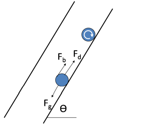
The Plate Settler Spacing team is currently investigating the Floc Roll-Up Phenomenon in the tube settler. By developing a velocity gradient model, we hope to both analytically and experimentally determine the critical velocity floc particles experience when they begin to roll up the settler tube and into the effluent rather than settling back down the tube and into the floc blanket. The critical velocity is determined using a force balance for a floc particle. In addition to determining this critical velocity, we hope to understand how properties of the flocs themselves affect floc roll-up.

Plate Settler Spacing - Experiments with Saturated Water, Fall 2009

Christine Lauren Catudal, Matthew William Hurst

This experiment explored the impact of water supersaturated with respect to atmospheric pressure on floc blanket formation and performance. This experiment involved collaboration with the Floating Floc Research Team, who supplied the saturated water that served as the influent water to the process.

Computational Fluid Dynamics Flocculation Tank Simulation, Fall 2009

Abstract:

Computational Fluid Dynamics (CFD) is a tool used by AguaClara to obtain a description of the flow through a portion of the plant where particle formation and growth (flocculation) occurs. This part of the plant is referred to as the flocculator. In this section, dirty (turbid) water flows through a series of baffles that enhances turbulent mixing. Essentially, for particles (flocs) to grow and eventually settle out in the sedimentation tank, they first must collide. By increasing the level of turbulence, the flocculator is increasing the collision potential of flocs. However, if there is too much turbulence, the flocs will break up and not settle out. By running CFD simulations of the flocculator, AguaClara can analyze the parameters important to flocculation and use the resulting data when making design decisions.

Computational Fluid Dynamics Flocculation Tank 3D Simulation, Spring 2009

Abstract:

The flocculation tank simulation team works on building a stable and reliable numerical model to simulate the flow inside the hydraulic flocculation tank, and providing well-studied guidelines for design, construction and operation of the flocculation tank.

Gravity powered hydraulic flocculators are used by AguaClara small-scale water treatment plants due to their low cost, inherent simplicity and robust operation. However, their inflexibility of energy input into the water relative to mechanical flocculators requires well studied design based on the understanding of the flow field and relevant performance parameters.

An appropriate CFD simulation can provide detailed numerical solutions for all the variables in the flow field, and by varying parameters such as tank geometry and flow conditions, we could obtain predictions of each of the flow variables and thus optimize the design towards lower cost and better performance.

Currently, our effort is focused on depicting an accurate energy dissipation map inside the flocculator, describing the size and the shape of the region where most of the energy is dissipated and the formation and collisions of flocs happen, thus providing basis for more efficient and economical design utilizing geometries that dissipate energy as uniformly as possible.

Chemical Dose Controller Retrofit Designs, Fall 2009

Abstract:

In some AguaClara plants, a surface foam develops at the end of rapid mix. The initial focus of the research was on the chemical conditions required for this surface foam to develop then the focus shifted to the fluid mechanics that make this occurrence possible and the simple retrofit designs that can ameliorate these conditions. In the initial experiments, different chemical conditions were tested for using a series of jar mixers and one-gallon tanks that modeled rapid mix. The first few trials tests ran a constant supply of clay with varying amounts of alum but these did not exhibit any form of surface foam formation. Subsequent trials included organic matter: humic acid, but these only produced large non persistent bubbles. It was not until a stronger surfactant, liquid soap, was added to the baffle spacing that a surface foam with strong persistent bubbles developed. From these experiments it was concluded that air entrainment along with a surfactant in the raw water are the main chemical factors behind surface foam formation.

Upon observing that waterfalls, like the one found in the LFOM, created the ideal fluid dynamic conditions for air entrainment; the second half of the research focused on retrofitting the LFOM at current AguaClara plants. The four designs that were suggested either used a submerged orifice, a vertical surface area or an inclined plane to decrease the velocity of the incoming water through the LFOM. In testing the viability of each design option the three limiting parameters of foam formation from water jets were recognized and documented.

Chemical Dose Controller Surface Foam, Summer 2009

Abstract:

In some AguaClara plants, a surface foam develops at the end of rapid mix. The initial focus of the research was on the chemical conditions required for this surface foam to develop then the focus shifted to the fluid mechanics that make this occurrence possible and the simple retrofit designs that can ameliorate these conditions. In the initial experiments, different chemical conditions were tested for using a series of jar mixers and one-gallon tanks that modeled rapid mix. The first few trials tests ran a constant supply of clay with varying amounts of alum but these did not exhibit any form of surface foam formation. Subsequent trials included organic matter: humic acid, but these only produced large non persistent bubbles. It was not until a stronger surfactant, liquid soap, was added to the baffle spacing that a surface foam with strong persistent bubbles developed. From these experiments it was concluded that air entrainment along with a surfactant in the raw water are the main chemical factors behind surface foam formation.

Upon observing that waterfalls, like the one found in the LFOM, created the ideal fluid dynamic conditions for air entrainment; the second half of the research focused on retrofitting the LFOM at current AguaClara plants. The four designs that were suggested either used a submerged orifice, a vertical surface area or an inclined plane to decrease the velocity of the incoming water through the LFOM. In testing the viability of each design option the three limiting parameters of foam formation from water jets were recognized and documented.

Turbidimeter, Spring 2011

Emily Clamp, Rohiverth Guarecuco, Julia Morris

Abstract:

The goal of the turbidity team was to create a low-cost turbidimeter that measures water turbidity within the range of 5 NTU to 250 NTU. Thus far, the team has brainstormed various turbidimeter designs and created several prototypes for simultaneously testing different LED display patterns. Many patterns have been assessed, including a dual-range LED display pattern for measuring a broad turbidity range. The dual-range LED pattern was tested using an experimental setup that allowed turbidity measurement of water that was constantly mixed with kaolin clay using a water pump. The team determined that only the fine pattern of the dual-range pattern was necessary, since the pattern alone could accurately measure turbidities from 5-200 NTU. This approach is based on resolution of the fine pattern within the turbidimeter as opposed to the use of contrast when using conventional Secchi disk patterns. The fine-resolution pattern was used to create a low-cost turbidimeter prototype equipped with an NTU scale based on the power-law equation derived from experimental results.

Tubidimeter, Summer 2011

Jennifer Gass, Maxwell Petersen, Heidi Rausch

Abstract:

The goals of this summer’s Turbidity team were to:

  • Finish the testing that the previous team had been working on in order to design a cheap (under $20) Turbidimeter that can easily be transported to potential AguaClara facility locations.

  • Find a relationship between depth and Turbidity that is within 50% accuracy for a specific disk design based on line thickness and spacing.

  • Fabricate and calibrate 10 turbidimeters that will be ready for shipment by July 28, 2011.

Thus far, the team has managed to improve the design of the original Turbidimeter while lowering cost and increasing portability. All ten prototypes were built, calibrated, and sent to Honduras by the specified date. The only shortcoming was that due to size limitations the Turbidimeter could not measure below 15 NTU, however, this does allow for greater ease of use. The final Turbidimeter design is just over 60 cm in height and costs $4.02 to make.

Turbidimeter, Fall 2011

Julia Morris, Andrew Gorodetsky, Heidi Rausch

Abstract:

This report will cover all the work that has been done by Cornell’s AguaClara program on turbidimeters. Research first started on creating a new, low cost turbidimeter at Cornell in the Spring of 2011. Since then several different prototypes have been created and ten turbidimeters have been sent to Honduras for use by communities who are considering building an AguaClara plant. The reason that a low cost turbidimeter needs to be developed is so that communities who may be in need of water treatment facilities can test their water without incurring the high expense of other turbidimeters currently on the market. The most current complete turbidimeter prototype can read NTU values down to 15 NTU. The research discussed in this report details new turbidimeter designs with which it may be possible to read NTU values down to approximately seven NTU. The most promising design includes the use of a blue LED light and a large HDPE block, which is used for diffusing the light. However, this design will need to be tested more thoroughly for accuracy before it can be fabricated for use in the field. In the future if research continues to be done to try to create a turbidimeter that can read turbidity values below 5 NTU the length of the lowering rod may have to be made longer than the current prototype, which is only 60 cm long. Without adding length to the lowering rod current research suggests that it may be impossible to read the turbidity of any water with an NTU value lower than seven.