2008 Summer — Research Archive — AguaClara Reach

2008 Summer

Float Valve Attenuation Factor, Summer 2008

Introduction:

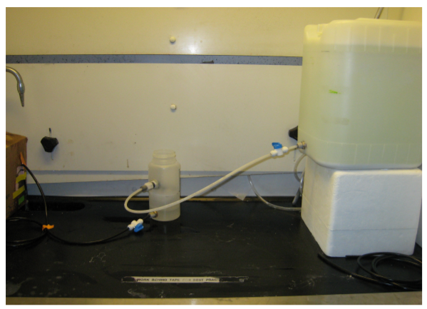
Until recently, the float valves used in the AguaClara's flow controllers were slightly flawed. The float valve connector included a compression nut, which was easily misplaced or misused, leading to leaks. A new float valve would preferably have pipe threads and be able to connect to a quick connect tube fitting. Furthermore, the float on the float valve was replaced in favor of another float, complicating post manufacturing assembly. A new float valve was found with pipe threads, quick connect tube fitting and had a more appropriate valve attached. However, before the new float valve was to be implemented, a study on the attenuation factor (change in pressure from stock tank over the change in pressure in the constant head tank) was to be conducted.

Calcium Hypochlorite Dose Controller, Summer 2008

Introduction:

In Honduras, a Calcium Hypochlorite solution is used in the Agua Clara flow controllers to chlorinate the drinking water. Unfortunately, due to the precipitation of calcium carbonate, the system clogs, which leads to large decrease in the flow rate (and thus dosing) of the chlorinating solution. The goal of these experiments were to find the contributing factors to failure (significantly decreased flow rate) by modeling a hypochlorinator in use in Honduras.

Alum Aging Effects, Summer 2008

Introduction:

To ease plant preparation for use, it may be beneficial to create stock solutions of required chemicals days in advance of actual operation. Because certain chemical solutions equilibrate with air, they may perform better or worse with age. Using this set of experiments, it was to be determined whether an aluminum sulfate solution produces lower levels of effluent turbidity due to its age.

Demo Plant, Summer 2008

Introduction:

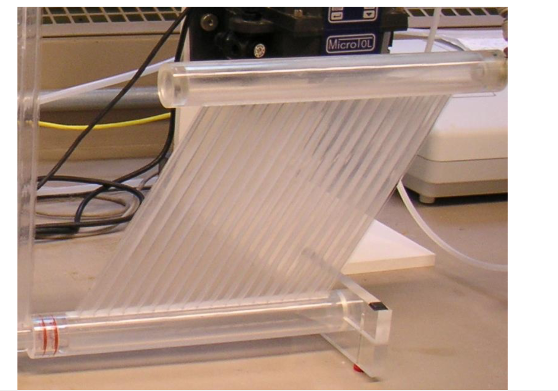
There are three variations of sedimentation tanks that the demo plant team can use. The purpose of these experiments were to find which sedimentation tank produced the lowest effluent turbidity when run at a number of flow rates. The preferre d tank will be used in the production of additional demo plants. The tanks are displayed below.

Flow Controller Calibration, Summer 2008

Introduction:

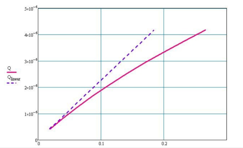
The flow controller design tool on the Flow Controller page is used to calculate the tube length necessary to achieve a desired flow rate with a certain head loss. It has been observed that the actual flow rates that occur when using the lengths of tube provided by the design tool were consistently much slower than they theoretically should have been. This indicated that there was some problem with the assumptions made by the design tool. The error was most likely due to one of two things. It was possible that the actual diameter of the tubing being used was slightly smaller than the diameter published by the manufacturer, or that there were significant minor losses in the flow controller not being taken into account by the assumption of a linear relationship between flow rate and head loss/tube length. It was decided that rather than having to manually calibrate every new flow controller, it would be better to come up with a new method for finding the tube length needed. The new method would need to take into account the smaller diameter of the tubing and/or the minor losses, and would predict a more accurate flow rate without having to do further manual calculations or having to cut the tube after construction of the flow controller