Structures, Spring 2011

Hyeong Yoon, Thomas Shouler, Joe Beaudette

Abstract:

Our main objective we wished to accomplish this semester was to create a means of automating the design of the columns and walls for the design tool. We began this work by analyzing the structural capabilities of the columns and walls for the Alauca plant.

There are three different load cases that guide the design of the columns and walls of the tank. The first case assumed that the tank walls were supported by the surrounding backfill. The second case assumed no support from this backfill. The third case analyzed the structural importance of the rubble which lies at the base of the sedimentation tank.

For our analysis of the walls, we modeled them as closely spaced columns. As seen in Figure 1, the vertical rebar that runs through these walls will add flexural support. By modeling the walls as columns we accounted for this vertical rebar. Modeling the walls as a combination of individual columns also allowed us to use the same tools and procedures that we used for the analysis of the columns. We set the moment at initial cracking as our first failure moment. We determined this moment by using the the Transformed Moment of Inertia method. We also wanted to know the moment that would render the walls and columns could experience before ultimate failure. We believed that this value would be of importance for future analyses which would incorporate earthquake conditions. For this ultimate failure analysis, we used the Column Interaction Diagram. This method plots the area of all axial load and moment cases that a column would be able to support safely. All methods are explained in detail in the report.

Validation CFD in ANSYS Fluent, Spring 2010

Validation Studies of Fluent Turbulence Models for Fluent Simulations of AguaClara Flocculators

Travis Stanislaus

Introduction:

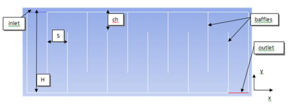
The AguaClara water treatment project uses ANSYS Fluent computational fluid dynamics (CFD) software to simulate and analyze turbulent fluid flow in idealized models of flocculators in AguaClara water treatment plants. The flocculator simulations in Fluent are used to obtain turbulent kinetic energy dissipation rate, ε, and energy loss coefficient, K, between baffle in the flocculator for AguaClara design equations that determine the height of the flocculator, H, the spacing between baffles, S, the quantity of baffles in the flocculator, and flocculation performance, Ѳε^(1/3) , Ѳ is the residence time between two baffles. The results from Fluent are used in the design of AguaClara facilities, so verification and validation of the Fluent flocculator model and simulation has been conducted continuously since the time AguaClara began using Fluent simulations. Verification is determination of the degree the model being simulated is an accurate representation of the developer’s description and solution to the model. Validation is determining if the model is an accurate representation of the real world physics and intended uses of the model.

Acid Neutralizing Capacity, Fall 2010

Drew Hart, Roy Guarecuco, Larry Lin

Abstract:

In light of recent successful tests run by the AguaClara Engineers in Honduras with poly-aluminum chloride (PAC), an alternative coagulant to alum which consumes a fraction of the alkalinity, the ANC Control team is preparing to stop research with lime feeders because they will be largely unnecessary when PAC is adopted for all AguaClara designs. In order to bring closure to ANC research the team will write a final paper detailing the insights pertinent to lime feeder technology that AguaClara has gained over five semesters of research. We will also organize the ANC Control wiki page

Acid Neutralizing Capacity - Summer 2010

Sang Hoon Song, Anna Lee, Roy Guarecuco, Drew Hart

Abstract:

AguaClara plants rely on sweep flocculation to achieve high performance requiring a pH between 6.5 and 7.5 even after the dosing of alum. The low alkalinity of Honduran source waters requires the addition of acid neutralizing capacity to buffer against changes in pH from the precipitation of aluminum hydroxide after alum addition. The summer 2010 ANC Control team has continued to investigate the possibility of using a lime feeder with AguaClara plants to deliver saturated calcium hydroxide solution to the plant flow. The team now believes that the inability of the lime feeder to produce saturated effluent for long periods of time is primarily due to the precipitation of calcium carbonate which inhibits Ca(OH)2 dissolution. Experimental runs with distilled water and Honduran lime have produced better results than those seen in past semesters, but only 15% to 20% of the total lime dissolves to give a saturated effluent, too little for the lime feeder to be economically viable compared to sodium carbonate dosing. The team has added effluent recycle to remove carbonates from the reactor influent, which will be tested by future teams. In addition, the team is closer to determining the composition of the lime using the Total Carbon Analyzer.

Acid Neutralizing Capacity - Spring 2010

Created by Chengfeng Wu, last modified by Lorna Ximena Aristizabal Clavijo on May 28, 2010

Abstract:

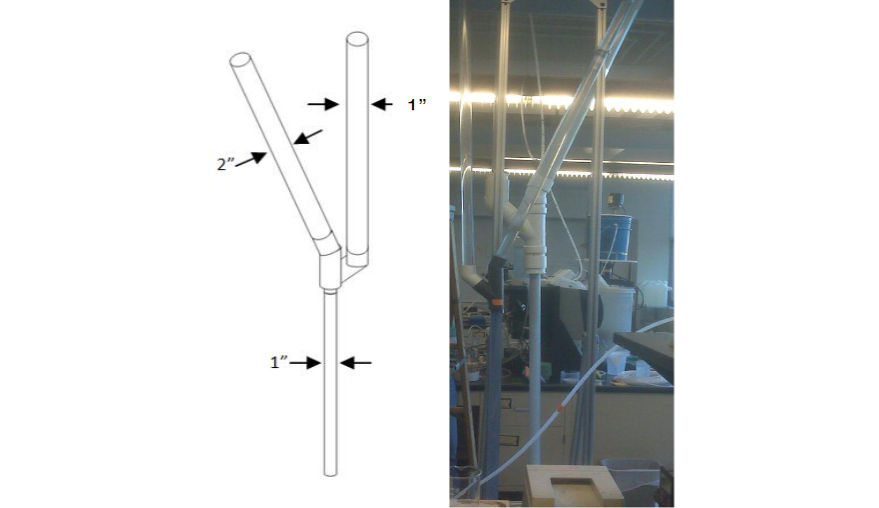
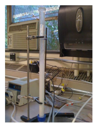
The Spring 2010 ANC team is continuing research with lime feeders where the Fall 2009 team left off. The original idea was to create lamellar sedimentation by placing a slanted tube on top of a vertical one and running water upwards through the reactor. With appropriate fluid velocities, one can maintain a fluidized bed of lime particles in the lower segment but prevent the vast majority of solid lime particles from leaving with the effluent (see 2009 design). This semester the team modified the reactor design in order to improve its performance and provide an easy way to feed lime while the reactor is running (see new lime feeder design).

Following the set-up described in each experiment found below with both the new apparatus and the old one, the team is conducting a series of experiments in order to determine which mechanisms are important in producing effluent saturated with lime for long periods of time. The tests are based on hypotheses which the team has developed over the course of the semester. Following the recommendation of previous ANC teams, the Spring 2010 team has tried to isolate variables and test them separately. In all of the experiments, the team has tried to vary only one parameter at a time so that comparisons between tests are more meaningful.

Chemical Dose Controller, Summer 2010

Monica Hill, Aditi Naik, Ritu Raman

Abstract:

The Summer 2010 Chemical Dose Controller (CDC) Team has spent the summer exploring the challenges associated with manufacturing precise orifices. The team has run a series of tests measuring flow rate on orifices created from Legris polyamide, flare cap fittings, refrigerator caps, and carburetor jets to determine their precision and accuracy. The orifices manufactured from polyamide were deemed inadequate, which caused the team to consider in- house and off-the-shelf manufactured orifices created from brass, which showed much lower deviations from the expected flow rate. This report describes the results of the team's experiments on four different types of orifices and endeavors to set future goals for next semester's CDC Team.

Plater Settler Spacing - Coupling Analysis, Spring 2010

Zachary N. Romeo

Abstract:

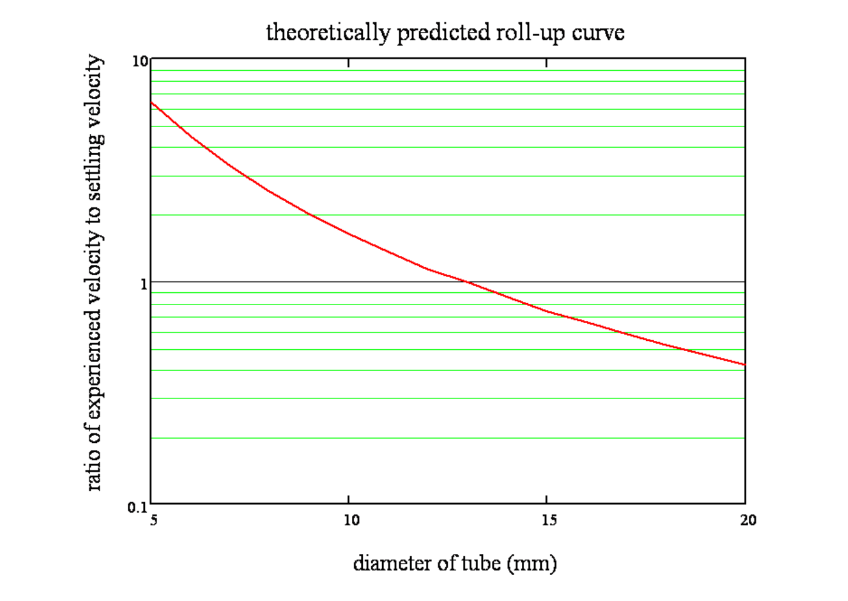
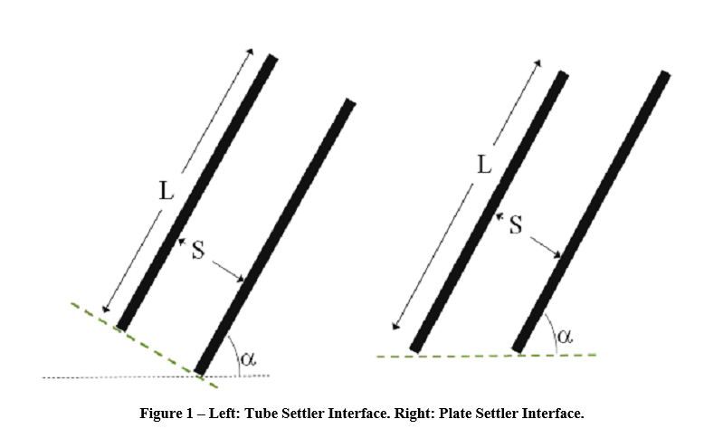
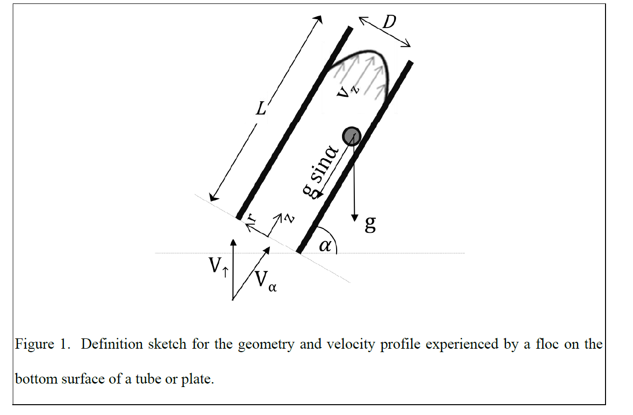
Floc roll-up occurs in tube settlers when the torque caused by a differential in the velocity profile exceeds the force of gravity whereby particles fall back out into the sedimentation basin. The Plate Settler Spacing team hypothesized that holding the length to diameter ratio in tubes of different diameters constant at 20 would decrease the capture velocity's sensitivity to flow rate. Two diameters representing the extremes in lamella spacing (23.5 mm and 6.35 mm) were tested in this experiment. Each experiment was run with the tube settler at two different heights (1.3 cm and 2.7 cm) above the floc blanket-clear water interface.

Plate Settler Spacing - Velocity Gradients, Spring 2010

Tanya Suntikul Cabrito

Stepping from previous research with velocity gradients, this experiment seeks to uncouple their effects on tube settler performance deterioration from those of the capture velocity. In the team's last experiments (detailed in Exploring the Coupled Effects of Capture Velocity on Settler Performance), it was hypothesized that maintaining a constant length to diameter ratio in tube settlers would minimize the effects of the capture velocity on performance.

Plate Settler Spacing, Fall 2010

Tanya Cabrito, Jae Lim, Cosme Somogyi

Abstract:

The goal of the Plate Settler Spacing Team (PSS) is to study the lamellar sedimentation process in plate settlers and the efficiency of the removal of flocculated particles and establish improved guidelines for plate settler spacing. The traditional guidelines for plate settlers state that the spacing between plates cannot be less than 5 cm and little to no justification can be found for this. The team's results show that performance in accordance with the US drinking water standard of 0.3 NTU can be achieved with spacings smaller than 5 cm. Also, all but one of the experiments meet the World Health Organization standard of 5 NTU. For AguaClara plants, having smaller spacings between plate settlers allow the sedimentation tank to be shallower and therefore cheaper.  Smaller spacings also allow for increased head loss across the plate settlers. This would help even out the distribution of flow in AC plants and allow the plate settler system to function at its design capture velocity of 0.12 mm/s throughout. The team had finished velocity gradient experiments with a clay aluminum hydroxide system; however, a recently discovered mistake in documentation caused the team to reassess the data collected this semester and more tube trials must be run. Due to this error, the team changed the capture velocity for the velocity gradient from 0.12 mm/s to 0.10 mm/s.  The major tasks completed by the Fall 2010 PSS team are catching a documentation error that happened at the end of Spring 2010, studying the effects of high velocity gradients and floc rollup on plate settler performance, developing a macro that significantly facilitates data analysis and a plate settler dynamics model that may better shed light into processes governing plate settler performance.

Non-Linear Chemical Dose Controller, Fall 2010

Abstract

Accurate alum dosing is vital for plant operation as it has a great impact on the effectiveness of flocculation and sedimentation. The nonlinear chemical dose controller (CDC) is designed to handle turbulent flow chemical dosing used in conjunction with the newly designed Rapid Mix Tube. In contrast, the linear CDC requires that the chemical flow in the dosing tube is laminar.

The linear CDC uses the linear relationship between laminar flow and major losses in the doser tube to maintain a constant chemical dose with varying plant flow rates. However, when the flow in the dosing tube is turbulent, the linear relationship no longer exists. In this case, a nonlinear CDC, one that uses minor losses to control flow rates, can be used to maintain a constant chemical dose with the varying plant flow rates. By using an orifice to control chemical flow, the CDC will have the same nonlinear response to increasing flow as the plant flow rate, which is controlled by an orifice. A dual scale system on the lever arm will increase accuracy in dosing at smaller doses.

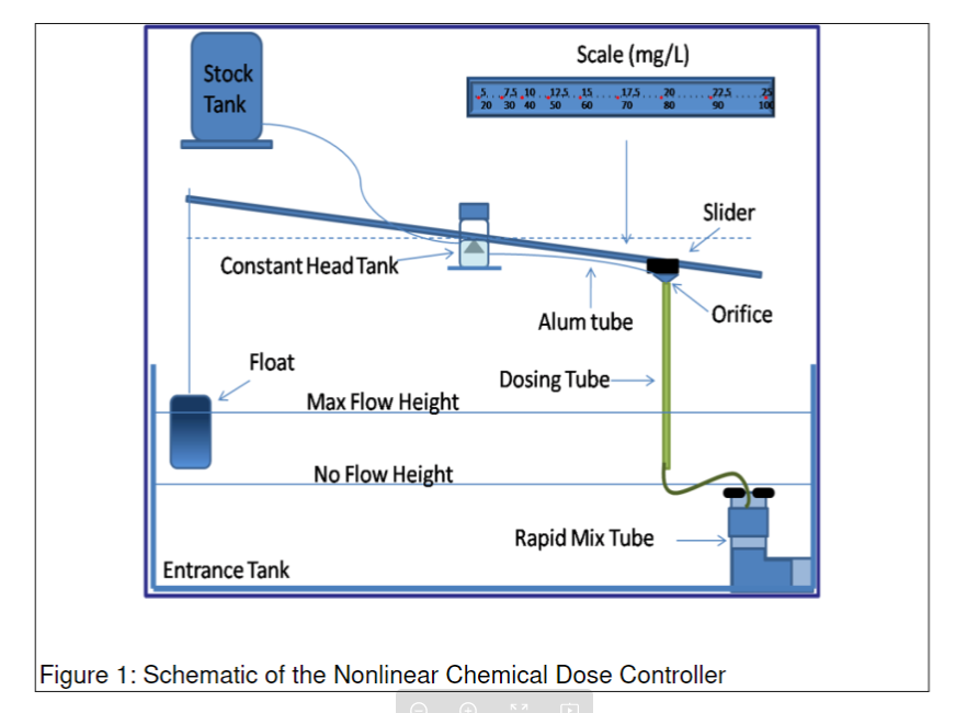
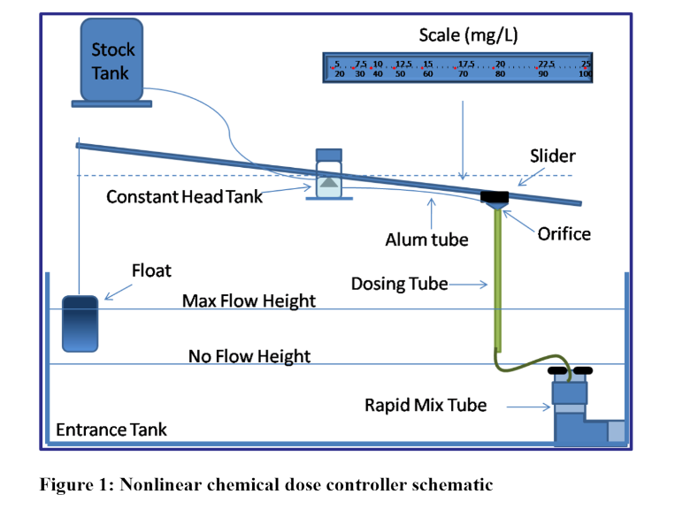
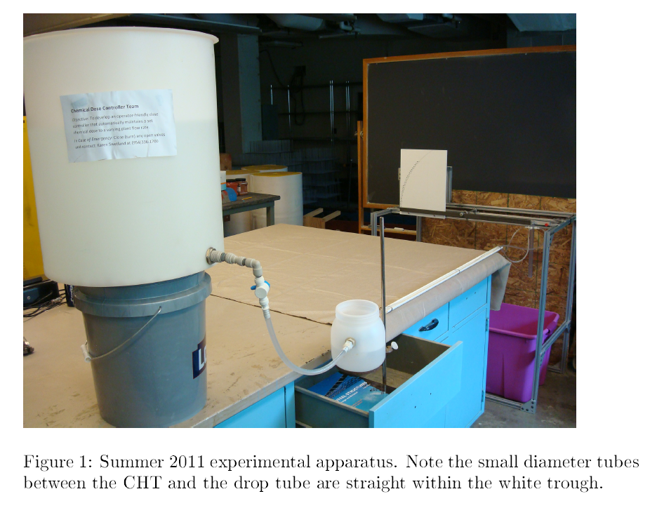
Figure 1 shows a conceptual design of the dosing system. A float in the entrance tank is connected to one end of the lever arm and allows for the arm to move up or down based on varying plant flow rates. As plant flow rates increase, the float rises, and the lever arm connecting the dosing orifice falls increases the elevation difference between the constant head tank and dosing orifice to power chemical flow. As the flow rate decreases the elevation difference decreases and the chemical flow rate slows down.

Figure 1: Nonlinear chemical dose controller schematic

There are two dosing tubes coming out of the constant head tank each with a different size orifice fitting attached to the end. The two different sized orifices allow for the plant operator to dose alum at two different scales, a high and low scale. The operator will choose which orifice will be used based upon the desired alum dose the operator wishes to apply to the water, a parameter that depends on raw water characteristics. The two scales on the lever arm, as seen in Figure 1, correspond to one of the dosing tubes; for instance, the higher scale (20-100 mg/L) will be used when the larger orifice size is needed. The dosing tube which is not in use is merely lifted to a higher elevation than the constant head tank level and is clipped onto a hook to prevent the flow of alum through this unused orifice.

After the alum exits the dosing orifice it flows down through a rigid tube which then injects the alum over a rapid mix conduit which connects the entrance tank and the flocculator. The rapid mix tube has two orifices which create macro and micro eddies to ensure the uniform distribution of coagulant into the raw water.

Laminar Tube Flocculator, Fall 2010

Tami Chung, Alexander O’Connell, Karen Swetland

Abstract

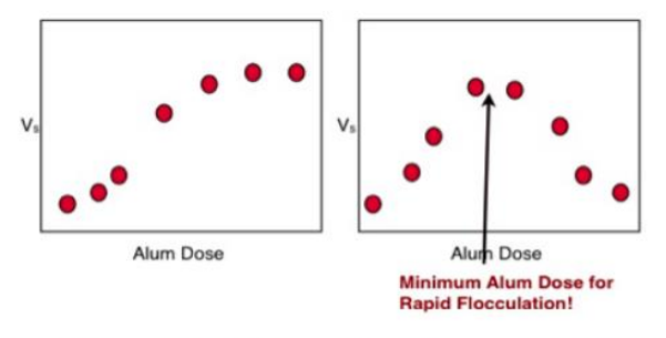
The Fall 2010 Tube Floc Team of aimed to better understand the development of rapid flocculation through a series of experiments and data analysis. In previous semesters, we had focused on the variation of flocculator length and alum dose. With the completion of these studies, we encountered more questions regarding the fundamental mechanisms involved in the process. As a result we chose to focus on characterizing the minimum coagulant dose needed to initiate rapid flocculation for two difference coagulants, alum and PAC. We hope to use this data in the future to develop a theoretical framework describing the onset of rapid flocculation. In order to accomplish this goal and to ensure the accuracy of our data we made a number of improvements and modifications to the FReTA apparatus this semester. We are currently in the process of collecting data and hope to complete our planned experiments by the end of the Fall 2010 semester.

Chemical Dose Controller Development, Fall 2010

Eva Luna, Drew Hart, Larry Lin, Roy Guarecuco

Abstract

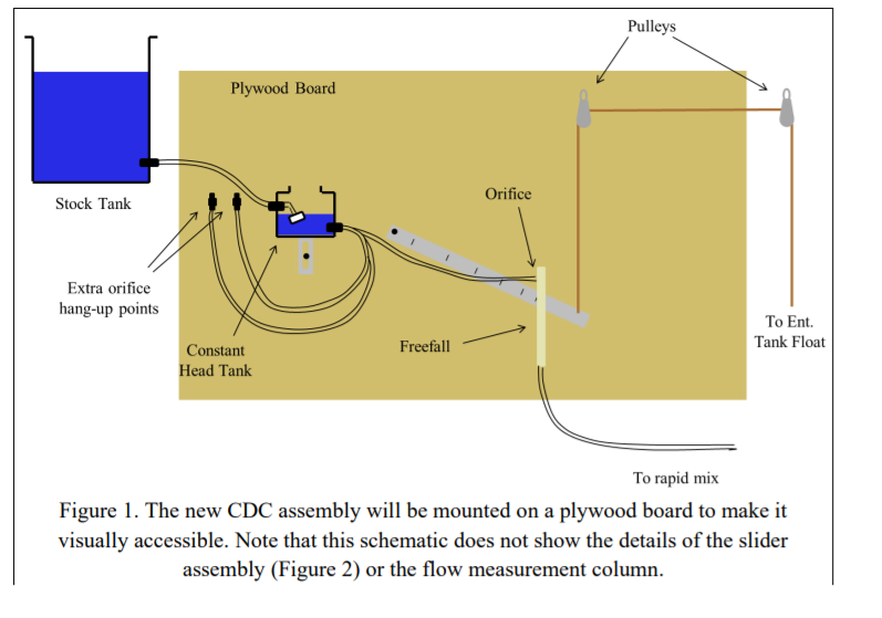
The Fall 2010 Chemical Dose Controller team has focused on designing the dose controller to be visually accessible, more aesthetically attractive, and robust. The apparatus will be mounted on a plywood board secured to the plant wall. The team has begun construction on a prototype for the design. In this report we have documented the design process and all of the component parts used in the prototype.

Acid Neutralizing Capacity, Fall 2010

Abstract

The ANC Control team has conducted laboratory research to investigate the feasibility of using a lime feeder to add alkalinity to the influent water of AguaClara plants. This was necessary in order to maintain the pH within the ideal range for flocculation after the addition the chemical coagulant, alum, which has an acidic effect. Low-alkalinity source waters in Honduras do not provide sufficient buffering capacity naturally to resist the drop in pH. The team has found that proposed lime feeder designs consistently fail to produce saturated effluent for a length of time which would make them economically and practically viable. The failure is believed to be caused by precipitation of calcium carbonate on the calcium hydroxide solid surfaces. The recent availability of poly-aluminum chloride, an alternative coagulant to alum with a much smaller acidic effect, in Honduras has reduced the need for lime feeders with AguaClara plants

Sedimentation Tank Hydraulics, Spring 2011

Yiwen Ng, Anna Lee, Tiffany Tsang

Abstract

Previously our team worked on designing a scaled down model of sedimentation tank in order to study floc blanket formation in 3D models. However, we decided that it would be more effective to continue the study with the existing 2D sedimentation tank. Using this tank our first objective was to determine the minimum angle of repose. We have hypothesized that for an insert angle below 60 degree that a floc blanket would not form. The slope of the insert would not be sufficient for the flocs to be transported to the jet, thus the flocs would accumulate on the incline. However, even when we decreased our angle of repose to 30 degrees, we were successful in forming the floc blanket.

Plate Settler Spacing, Spring 2011

The Effect of Floc Roll-up on Clay-Aluminum Hydroxide Flocs

Matt Hurst, Monroe Weber-Shirk*, Tanya Cabrito, Cosme Somogyi, Michael Adelman, Zachary Romero, Richard Pampuro, Rachel Phillipson, Sarah Long, Colette Kopon, Ying Zhang, Ashleigh Sujin Choi, Adela Kuzmiakova, Jae Lim, Alexander Duncan, Christine Catudal, Elizabeth Tutunjian, Ling Cheung, Kelly Kress, Tiara Marshall, and Leonard W. Lion

Abstract:

Inclined plate and tube settlers are commonly used to create compact sedimentation tanks. Conventional design guidelines are based on obtaining a desired sedimentation design capture velocity. Theoretically, this capture velocity can still be achieved while greatly reducing conventional plate spacing or tube diameter. The greatest concern with small plate spacing is the danger of settling sludge being swept out with the finished water. This research presents the basis of this failure mechanism as high velocity gradients present at small tube settler diameters and small plate settler spacings.

Plate Settler Capture Velocity, Fall 2011

Ruonan Zhang, Xiaocan Sun, Yizhao Du

Abstract:

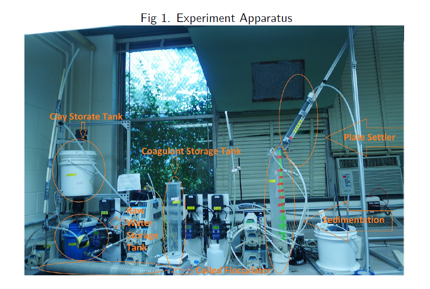
Through lab research we seek to understand the different influence of coagulant type, capture velocity, coagulant dose and raw water turbidity on the performance of the plate settler in AguaClara plants. We are using a tube settler to simulate those plate settlers in the full-scale plants. Through various changes in operating conditions, we expect to determine the best parameters, and this is of great significance in real practice. After that, we are going to pick out some of the best conditions and repeat the experiments with natural organics in order to see how humic acids affect overall performance.

Chemical Dose Controller, Spring 2011

Matthew Higgins, Adam Salwen, Christopher Guerrero

Abstract:

Accurate chemical dosing is important in water treatment plants to ensure optimal conditions for flocculation, sedimentation and disinfection of the treated water. The linear chemical dose controller uses laminar flow through a small diameter tube to create a linear relationship between head loss and chemical flow. The linear flow orifice meter then maintains a linear relationship between plant flow and water elevation. The linear relationships simplify chemical dosing for plant operators who may have a limited education. Our team is researching the upper-flow limit of the linear dose controller and developing innovative designs to increase the capacity of this system to function in plants with flow rates approaching and above 100 L/s. Furthermore, we are redesigning and simplifying the linear flow orifice meter algorithm to improve its precision and performance in the field.

Chemical Dose Controller, Summer 2011

Matthew Higgins

Abstract

Accurate chemical dosing in water treatment plants is imperative to ensure optimal efficiency during flocculation, sedimentation, filtration and disinfection. AguaClara designed the linear chemical dose controller (LCDC) and linear flow controller (LFC) systems to allow plant operators to reliably set and maintain a desired dose of coagulant and disinfectant. A linear relationship between head loss and chemical ow is created by using the major head loss through a small diameter tube to control the flow. To maintain this linear relationship, the systems have been designed to eliminate sources of minor head loss. Our team is actively working to minimize minor head losses through the systems, reduce the systems' maximum percent error and standardize the components and calibration techniques to be used to fabricate the systems in the field.

Chemical Dose Controller, Fall 2011

Jordanna Kendrot and Frank Owusu-Adarkwa

Abstract:

Continuous and accurate chemical dosing in water treatment plants is required for optimal efficiency during flocculation, sedimentation, filtration and disinfection. AguaClara designed the linear chemical dose controller (LCDC) and the Linear Flow Controller (LFC) systems to allow plant operators in Honduras to easily set and maintain the dose of coagulant and disinfectant through one system. A linear relationship between the head lost and chemical flow is created by using only major head loss, where the flow is controller by a small diameter tube. To continue using this linear relationship, the current experimental system has been designed with the goal of eliminating minor head loss. Our team is actively working towards the continuation of this work, decreasing the minor head losses throughout the systems, reducing the systems maximum percent error under 10% and standardizing the components and calibration techniques that will be used to fabricate this system in the field.